The Moxa E2210 Devices can transport Contact Closure signals to/from a device over Ethernet to the Teldio Edge Gateway (TEG). The Moxa E2210 is provided by Teldio.
Installing a Moxa E2210 Device at your location requires:
- A Power source
- A Network connection
- An IP address for the Moxa E2210 that is able to communicate with the TEG
- Dry or Wet Contact Closures to trigger alarms
The following sections detail how a Moxa E2210 device can be set up to communicate with the Teldio Edge Gateway.
Locating and Setting up the Moxa E2210 Device
The Moxa E2210 device has a default IP of 192.168.127.254. To access the Moxa E2210, change the IP of your computer/laptop to be 192.168.127.200 and connect the E2210 to be on the same network as your computer and power it on.
- Download, install and run the Moxa IO Admin program: http://files.teldio.com/support/ioAdminSetup.msi
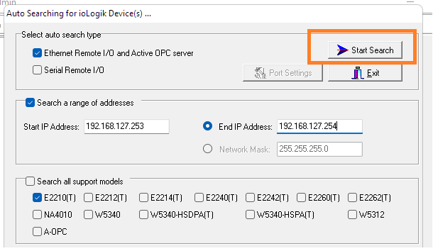
- On the pop up that appears, set the settings as shown below and click on the 'Start Search' button.
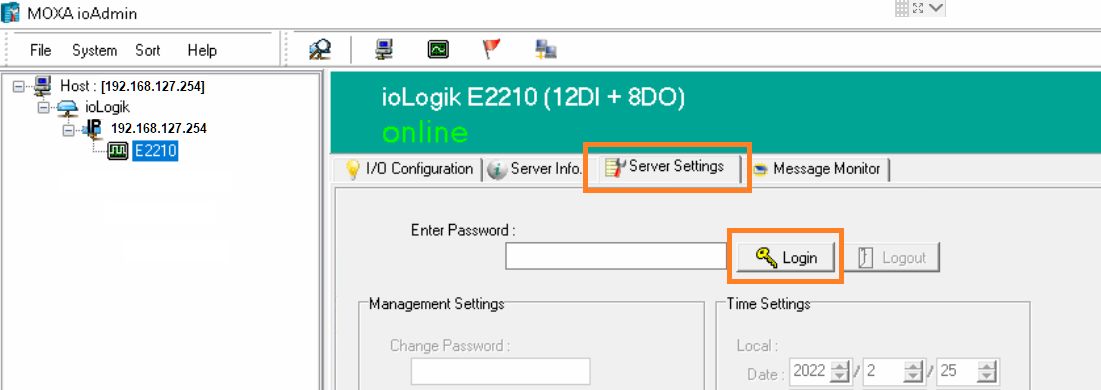
- The Moxa Device(s) will appear in the results section. Double click on the Moxa device you wish to edit. This will open up the ioLogik window.
- Click on the E2210 entry on the left
- Then click on the 'Server Settings' tab
- Then click on 'Login'. The password can be left blank.
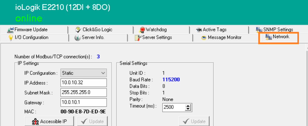
- Once you log in, click on the 'Network' tab and then change the IP to your desired IP address and click on Update.
Moxa E2210 Wiring Instructions
The Moxa E2210 can be setup to send alarms to the TEG or receive alarms from the TEG to raise alarms in other systems.
The data sheet of the Moxa E2210, which specifies the voltage needed for certain types of Contacts can be found here: Data Sheet
Wiring a Dry Contact as an Input to the Moxa E2210
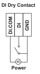
The Moxa E2210 has 12 inputs. The following diagram shows how a dry contact from an alarm source can be wired in to the Moxa E2210. A dry Contact does not need to be connected to a power source to function properly. You can connect up to 12 inputs, from DI0 to DI11, in to the Moxa E2210.
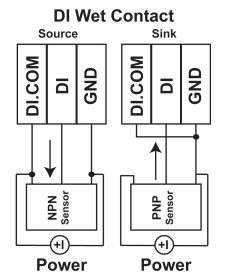
Wiring a Wet Contact as an Input to the Moxa E2210
The Moxa E2210 has 12 inputs. The following diagram shows how a wet contact from an alarm source can be wired in to the Moxa E2210. A wet Contact must be connected to a power source to function properly. You can connect up to 12 inputs, from DI0 to DI11, in to the Moxa E2210.
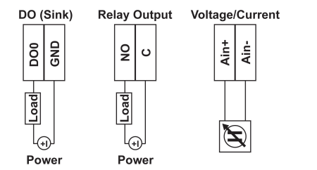
Wiring a Contact as an Output from the Moxa E2210
The Moxa E2210 has 8 outputs. The following diagram shows how a contact can be wired in to an alarm panel or device to receive alarms from the Moxa. You can connect up to 8 outputs, from DO0 to DO7, from the Moxa E2210.
Teldio Edge Gateway Settings
Once the Moxa E2210 is setup, the following configurations should be set up on the TEG to make it communicate with the E2210
Adding the Moxa E2210 to the TEG
- Log In to the TEG
- Go to Settings and then select Add Module
- Search for the MODBUS TCP 1-bit Client Module and click on ADD
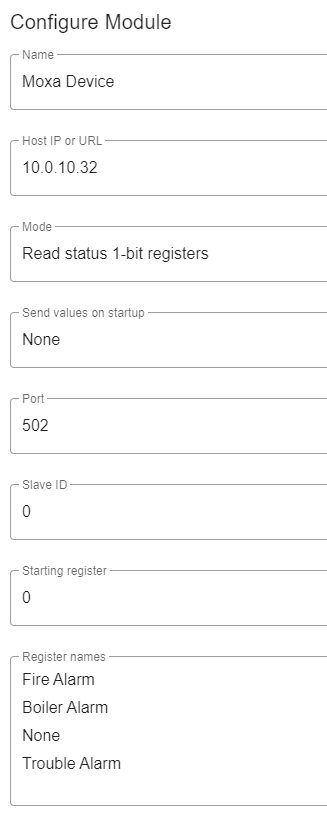
- Set the Name as desired
- Set the Host IP or URL to be the IP of the MOXA E2210
- Leave Mode as 'Read status 1-bit Registers'
- Leave the Starting Register as 0
- If using the Moxa as an Input to the TEG: Under Register names, input the text for your alarms, one line at a time. The first line will correspond to the DI0 input (as the Starting Register is 0), the second line will correspond to the DI1 input and so on.
- Press SAVE
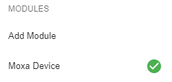
- The Moxa E2210 will now show up underneath the list of added Modules. A green checkmark will indicate that the TEG is able to communicate with the E2210 over the network. The module is now available to insert in to Behaviors to enable Workflows in the TEG.
Setting Up Behaviours
If using the Moxa as an Input to the TEG
- Setting up the Trigger:
- Module: Select the MODBUS TCP 1-bit Client module
- Event: Register Changed
- Filter:
- Value: Set to filter on True or False
If using the Moxa as an Output from the TEG
- Setting up the Action:
- Module: Select the MODBUS TCP 1-bit Client module
- Event: Select output
- Configure Action
- Set Output address: Set to the output Pin #
- Value: Set to 1 or 0